4 Pin Relay Diagram EdrawMax EdrawMax Templates
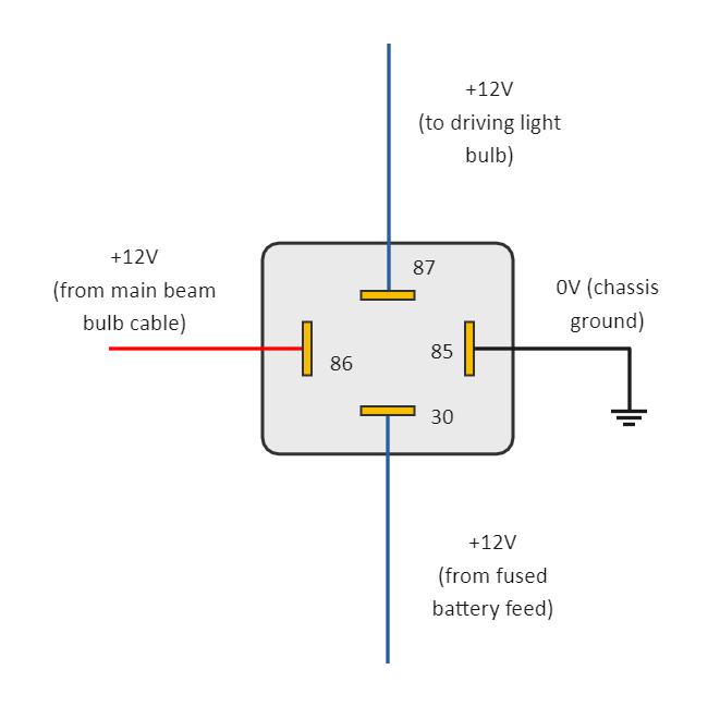
1. Identify the wires of Headlights: The first step in order to wire the relay for the driving light is to identify the wires coming out of the driving lights. Normally, there are two wires connected to these lights out of which, one is the power wire, normally having a red color, and another one will be ground wire black in color. 2.

4 Pin Relay Diagram 12 Volt Car Relays Used In Automotive Industry
In this video I show you how to wire a 12 volt automotive Bosch style relay. This video covers both 4 and 5 pin 12VDC relays.Best Connections - 12voltwire.co.
12v 40a Relay 4 Pin Wiring Diagram Naturalfer
Learn how to wire a standard 4-pin automotive or powersports relay in this quick video.

Basic Relay Circuit Diagram
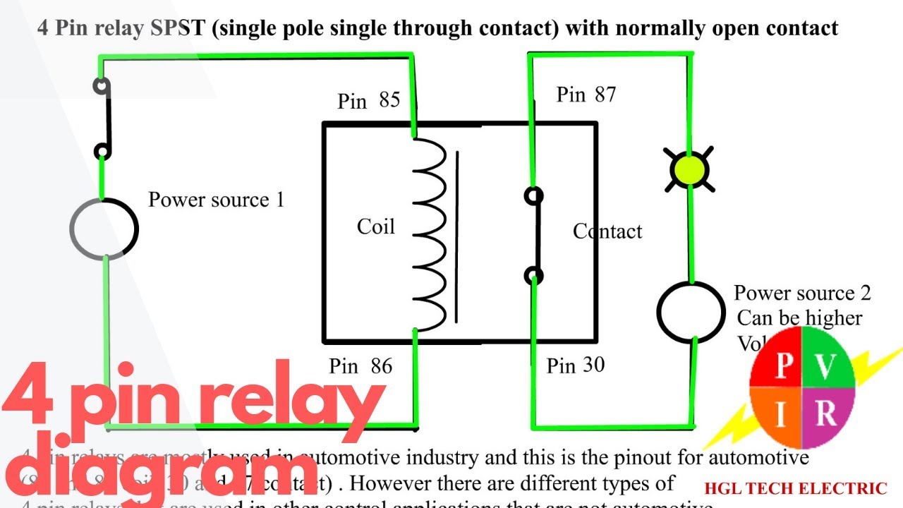
Wiring 4 Pin Relay: A Comprehensive Guide. A 4-pin relay is a commonly used electrical component that allows you to control a high-current circuit using a low-current signal. It is widely used in automotive applications such as controlling lights, horns, and motors. Understanding how to properly wire a 4-pin relay is essential for anyone.

Ford 4 Pin Relay Diagram
In this article, we will provide wiring diagrams of 4 pin and 5 pin automotive relays to help you better understand the wiring process. We'll start with a brief overview of what relays are and why they are important for your electrical system.
4 Pin Relay Wiring Diagram Cadician's Blog
This article will show you the wiring diagrams of different relays. You will learn how to connect 4-pin (SPST), 5-pin (SPDT), and 8-pin (DPDT) relays to a circuit. In general, there are only two types of relay you will ever use: breadboard/PCB friendly relay (for simple electronics projects) and automotive relay (used in automobiles).

Relay Wiring Diagram and Function Explained ETechnoG
1. Thinner cables can be used to connect the control switch to the relay thereby saving weight, space and cost. 2. Relays allow power to be routed to a device over the shortest distance, thereby reducing voltage loss. 3. Heavy gauge cable only needs to be used to connect a power source (via the relay) to the device. Why Use a Relay in a Car?

How To Wire A 4 Pin Relay
To wire a four-pin relay for driving lights, the first step is to use a fuse to connect the 12V battery to the Pin 30 of the four-pin relay. The reason why we connect the relay via a fuse instead of directly establishing a connection with the battery is to avoid any over currents.
Dorman 4 Pin Relay Wiring Diagram
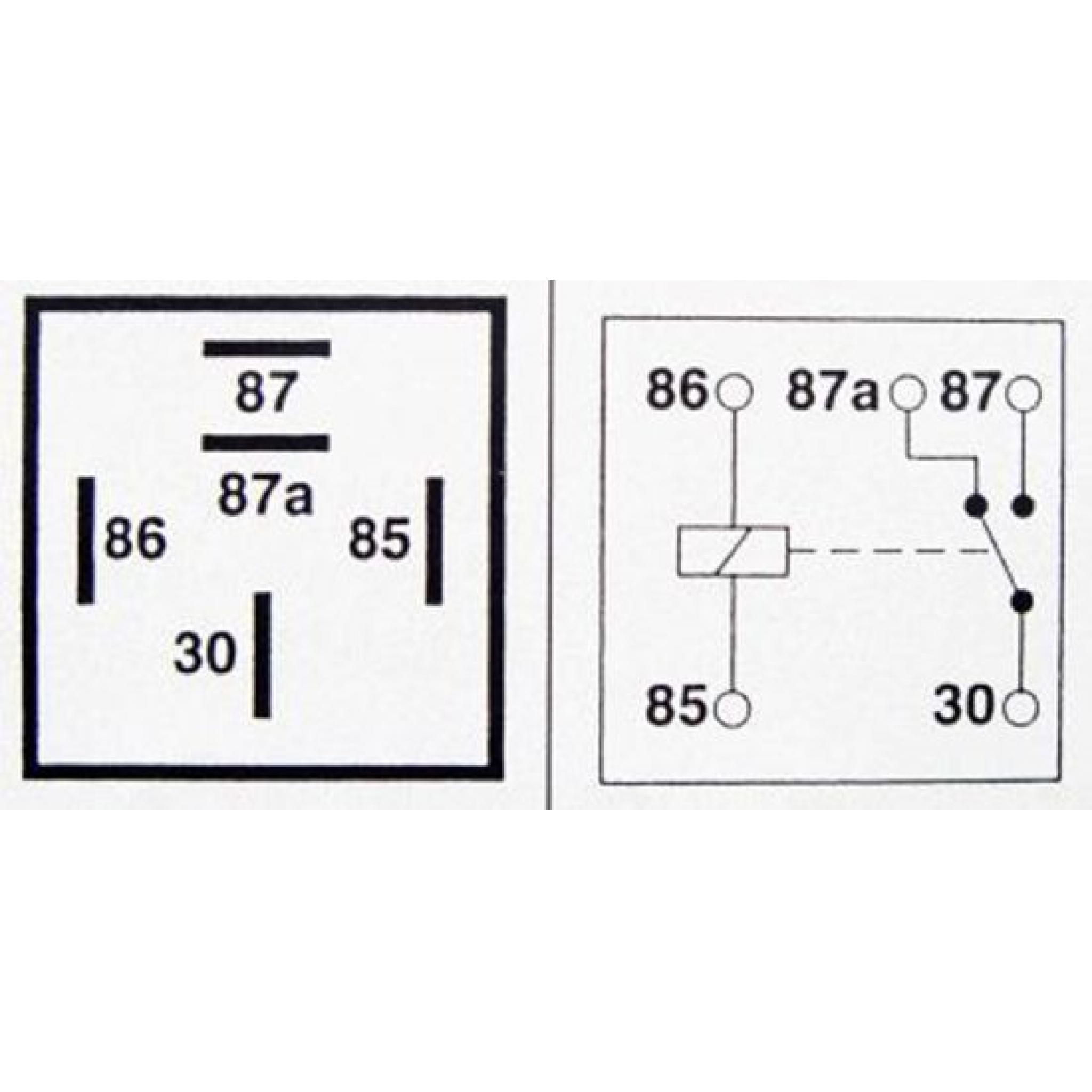
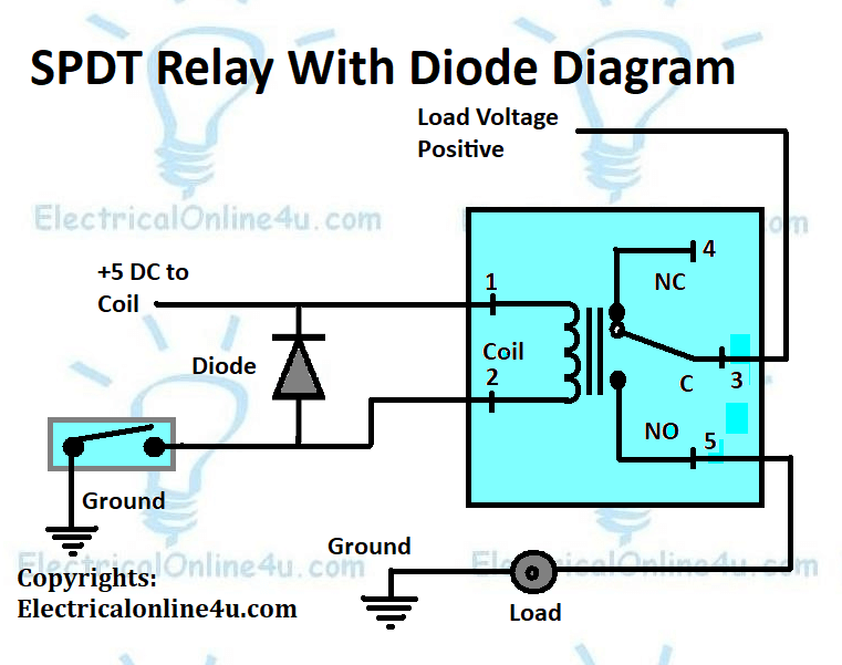
To understand the 4 pin indicator relay wiring diagram, you start from the left side of the diagram. You can see the N.O., N.C., Coil, and Common pins. The diagram shows the source of the electricity and its connections to the other pins in the relay.
Automotive Relay Wiring Diagram
Parts of a 4 Pin Relay Switch Diagram. When looking at a 4 pin relay switch diagram, the most important parts to look at are the pins, terminals, and the control circuit. The pins are the small metal connectors that connect the relay to the load (such as a light, motor, etc.). The terminals are the larger metal connectors that connect the power.

4 Pin Relay Wiring Diagram
By understanding the wiring diagram and following the correct connections, you can effectively utilize a 4 pin relay with a switch in various applications. Pin Relay Wiring Diagram with Switch. A relay is an electrical device that helps control a circuit by allowing a low-power signal to control a high-power circuit.
Denso 4 Pin Relay Diagram
A diagra.more.more This video is about how to wire an automotive relay switch. A relay is a switch that is turned on by a switch on the dash. The power going to the lights gets.

12v 30a Relay 4 Pin Wiring Diagram Wiring Draw And Schematic
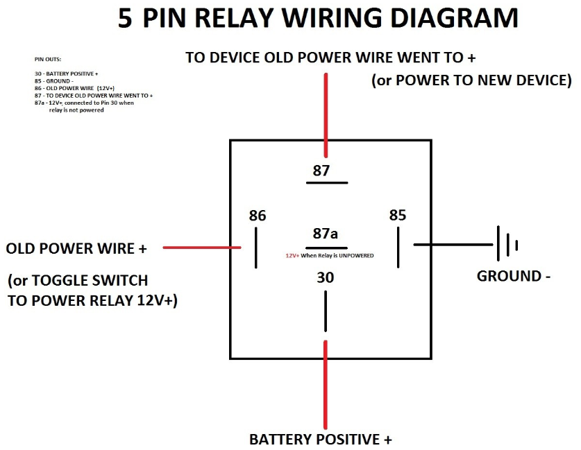
4-Pin-Relay-Wiring-Diagram Installing a relay is not a hard task provided that you know the schematics of the relay. Before installing the relay, you should understand the wiring diagram of the relay. First, we will explain the four and five-pin relay wiring diagram so that you have a good understanding of the relay diagram.

Relay Wiring Diagram 4 Pin
A 4-pin relay is an electromechanical switch that controls the flow of current between two circuits. It consists of four terminals: two coil terminals and two switch terminals. The coil is energized when a small current flows through it, activating the switch to allow a larger current to flow in the main circuit.
Relay Wiring Diagram A Complete Tutorial EdrawMax
A 4 Pin micro relay wiring diagram will usually show the diagram symbol and its associated label, the wire number and color code, the list of contacts or coils, the wire ratings and ampacities, the terminal number, and the overall drawing. It may also include items such as dimensions, pinouts, and mounting holes for connection points.

4 Pin Relay Connection Diagram Smart Thermostat Wiring
A 4 pin relay wiring diagram is a schematic representation of how to connect a relay to a circuit. Understanding and using this diagram is crucial for anyone working with electrical systems, whether you're an amateur or a professional. In this step-by-step guide, we will break down the components of a 4 pin relay wiring diagram and explain.
